Description
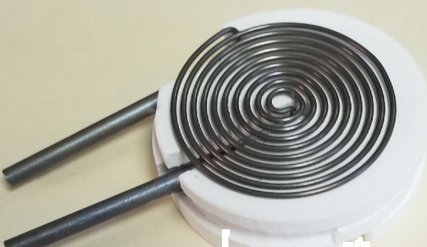
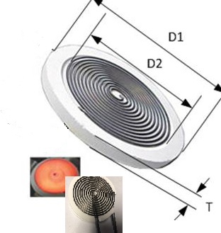
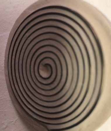
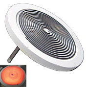
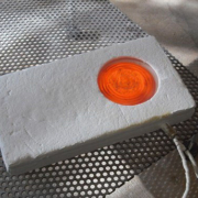
Special Pre-heater in Additive Manufacturing. MHI GAXP Spiral Microheater 1400C (OD=1″) MC-AM-1-30 3 layer. In plane terminals. Diameter D1= 25mm T= 5mm (3X for three layers).
Approximately 250 Watts [10V @ 27A (RMS)]. 3 layers of ceramic base included each ~5 mm thick.
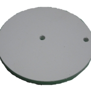
** Power reported under free radiating/ no-load condition with heater resting on provided ceramic plate. Horizontal use only – do not invert. Three ceramic bases included with the MC-AM-1-30.
Connectors comprise of One set of appropriately rated connecting clips and 5 to 8″ braided wire.
Alumina ceramic is rated to 1800C.
Note that the maximum current/power will be different (lower) if covered. Please do not exceed limits of current, voltage or element temperature.
For more information please visit our GAXP Spiral Microheaters page
For more information on the BPAN-O-PLUS controller please click to the Power and Temperature Control Panel Pages.
For controls choose either
- Feedback controls namely BPAN-O-PLUS-120T and Transformer. For customers who do not have a 120V wall supply, a 220V to 120V transformer will be added at no extra cost, or
- Open Controls with no feedback i.e. the DC Power Supply and a TC Read
Please choose BPAN-O-PLUS-220 when more than 3 units of the 2″ Spirals are placed in series
Only the BPAN-O-PLUS 120T (120V) option should be chosen when a single 2″ unit is used.
Leads should be able to carry the current e.g 10 AWG wire.
Alumina ceramic is rated to 1800C.
When checking out, the weight will be calculated with the control panel option.
The correct weight and shipping price will be shown in the final acknowledgement from MHI.
In the diagram D1 and D2 are separated by 0.1″ T is 0.25″ and H is 2.5″. D1 is the OD=1″.
There is no hole for a TC per se, however the ceramic is easily bored at a point of your choosing and for your T/C bead diameter. Please note that the only correct way to measure temperature for such a configuration is with an optical pyrometer. One will be able to calibrate the current with the temperature or power output. A current (amps) vs pyrometric measured temperature is provided below – when a TC is placed at any position and the current is monitored – one can then calibrate the TC reading (at the t/c placement location) with the actual pyrometric temperature – within reasonable error. The curve below should be use cautiously (only for general guidance) as it pertains to free radiating conditions only. Note that very often the TC reading that you measure will show a number well below the actual pyrometric temperature. Calibration is required when using t/C.



 MHI In. USA
 MHI Inc. USA
 MHI Inc. USA
 MHI Inc. USA


 MHI Inc. USA
 MHI Inc. USA