


Description
Please see the specifications below:
This product page is for panels for bottom heating. For vertical use panels, please click here.
For additional technical information or purchase, please contact MHI at 513-772-0404 or [email protected] or order directly through this store. For the replacement element (only) for an existing panel, please click here.

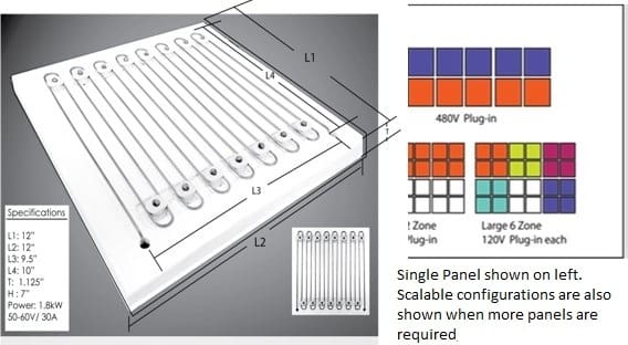
Mechanical Dimensions Per Panel. Please refer to the diagram above for dimensions. For layout possibilities, please see diagram alongside.
Dimensions
| Dimension | Value |
|---|---|
| L1 | 12 in |
| L2 | 12 in |
| L3 | 9.5 in |
| L4 | 10 in |
| T (Insulation Thickness) | 1.125 in |
| Lu (Terminal Length) | 7 in |
Specifications:
MHI URP Heating Panel Specifications
Product Overview
The MHI URP Heating Panel is a universal, scalable radiant heating panel designed for high-temperature furnace and thermal processing applications.
Each panel utilizes proprietary GAXP flat heating coils and Fractalin ceramic spacers, securely mounted on a thermal shock-resistant insulation slab. The panel is intended as a modular building block for furnace systems.
Important Safety Notice:
Furnace enclosures should only be designed and assembled by qualified personnel and with approval from a licensed electrician. These panels operate at high current and can reach extremely high temperatures.
Operating Characteristics
- Nominal Power per Panel: ~1.8 kW
- Maximum Coil Temperature: 1200°C–1400°C
- Recommended Maximum Coil Temperature: 1350°C
- Measured with a two-color optical pyrometer
- Orientation: Horizontal use only
- For vertical applications, select the URP-V Vertical Panel
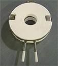
- Two electrical terminals are located beneath the ceramic board (not shown).
- Minimum 4 URP Panels required for 220 V UL BPAN
Electrical Specifications
Per Panel
| Specification | Value |
|---|---|
| Maximum Voltage | 55–58 VAC |
| Maximum Current | 30 A RMS |
| Nominal Power | ~1.8 kW |
| Maximum Coil Temperature | 1350°C |
Voltage Configurations
- 1 Panel: 55–58 V operation
- 2 Panels in Series: Approximately 110–120 V operation
- 4 Panels in Series: Approximately 220–240 V operation
Operating Limits
Never exceed the rated:
- Voltage
- Current
- Power
- Coil temperature
Failure to observe these limits may result in equipment damage or unsafe operation.
Control System Options
The URP panel may be operated using the MHI BPAN-O-PLUS Control System.
For assistance selecting controls, contact:
- Email: [email protected]
- Phone: 513-772-0404
Recommended Control Configurations
One URP Panel
- BPAN-O-PLUS Control
- BPAN-O-PLUS-120 or
- BPAN-O-PLUS-220
-

BPAN UL with stand
- Power transformer required unless matched to voltage

Two URP Panels in Series (110–120 V)
- BPAN-O-PLUS-120
- No transformer required
- Electrical outlet must be capable of supplying 30 A minimum
Two URP Panels in Series (220–240 V Source)
- BPAN-O-PLUS-220
- Transformer required to convert 220–240 V to 110 V
Four URP Panels in Series
- BPAN-O-PLUS-220
- No transformer required
Temperature Control Requirements
For proper operation, select:
- A compatible thermocouple for the BPAN-O-PLUS controller
- A thermocouple extension wire for each thermocouple used
- An over-temperature protection thermocouple
Panel Connection Options
Series Configuration
- Two panels may be connected in series for 110–120 V operation.
- Four panels may be connected in series for 220–240 V operation.
Series-Parallel Configuration
Balanced series-parallel wiring arrangements may also be used (refer to connection diagrams).
All electrical and thermal measurements are reported under free-radiating conditions.
Terminal Details
- Terminals extend approximately 6 inches from the rear side of the insulation board.
- Custom terminal lengths may be available for quantity orders.
Connector Option
Optional connector sets include:
- Two clip-type connectors
- Two lead wires (one for each terminal)
Connector Specifications
| Specification | Value |
|---|---|
| Current Rating | 35 A |
| Standard Wire Length | 6 in |
Custom wire lengths beyond the standard 6 inches are available upon request. Please contact MHI for details.
Shipping Information
- Shipping weight is calculated based on the selected control panel option.
- Final shipping weight and charges will be confirmed in the official order acknowledgment provided by MHI.
Contact Information
MHI Inc.
- Email: [email protected]
- Phone: 513-772-0404
For layout configurations, custom terminal lengths, connector extensions, or control system selection assistance, please contact MHI directly.
Four panels may be connected in series for a 220-240V plug-in configuration. Balanced series-parallel connections may be used (purple and red in the picture). All measurements are reported in the free radiating mode. 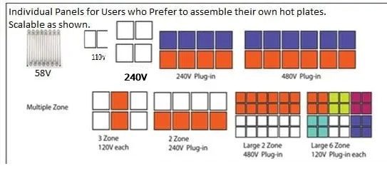
For layout possibilities, please see diagram alongside.
L1 = 12″
L2 = 12″
L3 = 9.5″https://mhi-inc.com/contact-us-request-information-about-mhi-products-or-for-general-inquiries/
L4 = 10″
T= 1.125″ (thickness of thermal shock-resistant insulation slab below the heater coil).
Lu = 7″ (Terminal Length). The terminals protrude about 6″ from the bottom of the insulation board (on the other side of the heating face). Use may request shorter Lu with quantity purchase.
Options:
The connectors comprise clip-type connectors (used to connect the wire and solid terminal) and two wires. One set, when chosen from the options menu comprises two clips and two wires i.e one for each lead. The rating of the connectors is 35 amp wire carrying capacity. Dimension – 6″ wire.
If required to extend beyond the 6″ standard, please contact MHI, and we will happily accommodate the request as best as possible.
The weight will be calculated with the control panel option when checking out.
The correct weight and shipping price will be shown in the final acknowledgment from MHI.

 MHI Inc. USA
 MHI Inc. USA
 MHI Inc. USA
 MHI Inc. USA










 MHI Inc. USA