Description
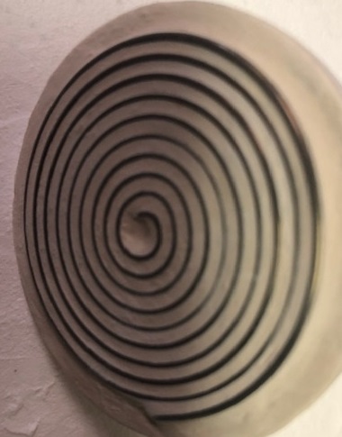
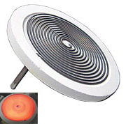
- MHI MC-GAXP-30-V Spiral Microheater For Vertical and Upside-Down Use.(1″ Diameter)
- 1200-1250C is the maximum temperature of the element in a vertical configuration.
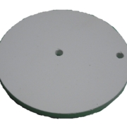
- Ceramic Base and End Connectors Included
Maximum ~250** Watts [10V @ 22A (RMS)]. Please note that the maximum values are reported for free radiating with minimal natural convection. Your values are likely to be lower.
** Power reported under free radiating/ no-load condition
Approximately 200-250 Watts. Please monitor to have less than [10V and less than 22A (RMS)**]. The highest values are for an entirely free radiating unit with natural or convective heat flow. Please monitor the temperature with a pyrometer or similar device and monitor the current and amps not to exceed any maximum condition. While heating up beyond 8 V and 19 Amps, please verify that the pyrometer temperature does not exceed 1200-1250C. Very rapid heating of vertical microheaters may cause some delamination.
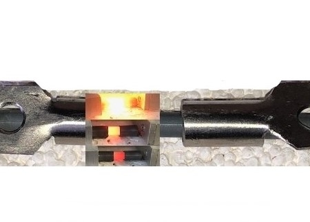
Connectors comprise One Set of Appropriately rated connecting clips.
Please note that limits cannot be exceeded on current, voltage, and element temperature.
Note that the maximum current will be different ( lower) if the unit is covered.
Leads should be able to carry the current, e.g., 10 AWG wire.
The base alumina ceramic is rated to 1800C. For more information, please visit the MHI GAXP Spiral Microheaters page.
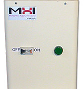
For control options, please choose either the Feedback Controls (recommended) or Open Loop Power Controls.
- Feedback controls: BPAN-O-PLUS-120T and Transformer. (For customers who may not have a 120V wall supply; a 220V to 120V transformer will be added at no extra charge when the BPAN-O-PLUS control system is ordered) or the
- Open Loop Power Control has no feedback feature; for this option, please choose the (DC Supply with TC Read). Please also order the TC and TC extension wire.
For more information on the BPAN-O-PLUS-120T controller, please click on the Power and Temperature Control Panel Pages.
The weight will be calculated with the control panel option when checking out.
The correct weight and shipping price will be shown in the final acknowledgment from MHI.
• Note that the maximum temperature is at the center of the spiral region unless asymmetric power delivery is required
• For obtaining maximum temperature MHI controls are highly recommended.
• Large diameter GAXP® microheaters could develop some springiness from induced magnetic forces.
• Potting in ceramic paste is allowed as long as care is taken to factor-in the loss of any thermocouple response in the measured temperature.
• Note element temperature will be higher and maximum element temperature should not be exceeded.
• In the free radiation mode the power can be maximized.
The objective of the use for free radiating devices is to maximize the radiative POWER transfer from the heating elements. If the heating element is covered with insulation, the objective of the user changes to obtain a certain temperature inside the insulated region.
The control of temperature inside a chamber, or power maximization in a free radiating mode can be made with MHI temperature and/or power controllers. When covered the power and current will be lower and the element temperature can be exceeded quickly if not monitored and controlled.
For either objective, one cannot exceed the rated temperature or maximum current of the heating element. Power output will be lower in enclosed radiation mode with a temperature control feature as opposed to or in addition to the power control.
Dimensions:~1″
Ceramic Base: as shown
Overall Length (including terminals) – 2.0”
Terminal Length (bottom of ceramic base to end of terminal) – 1.750”
Thickness of Ceramic Base – .250”
Weight – 20.75 gm
Approximately 250** Watts [10V @ 27A (RMS)]
There is no hole for a TC per se, however the ceramic is easily bored at a point of your choosing and for your T/C bead diameter. Please note that the only correct way to measure temperature for such a configuration is with an optical pyrometer. One will be able to calibrate the current with the temperature or power output. A current (amps) vs pyrometric measured temperature is provided below – when a TC is placed at any position and the current is monitored – one can then calibrate the TC reading (at the t/c placement location) with the actual pyrometric temperature – within reasonable error. The curve below should be use cautiously (only for general guidance) as it pertains to free radiating conditions only. Note that very often the TC reading that you measure will show a number well below the actual pyrometric temperature. Calibration is required when using t/C.



 MHI Inc. USA


 MHI Inc. USA