MHI Airtorch® Easy Power Calculation Method
For flow calculations, please contact MHI.
Energy Savings with MHI Airtorch®.
From 2 KW to 16 MW, 30MW, or even 100MW.
Energy and Environment Improvement with an MHI Airtorch®. Click here.
Calculating Power: The two equations below can be used for approximate power calculation for a known flow-rate between 0 and 1000C for air for a efficient process air heater.
Power in (kW) = SCFM . (DTc)/1755 where (DTc) =Temperature difference in Centigrade
Power in (kW) = SCFM . (DTF)/3160 where (DTF) = Temperature difference in Fahrenheit
SCFM = Standard cubic feet/minute for the airflow i.e., at 0C (32F), 14.69 psi (103.14 kPa) = 1.699 Nm3/h (standard cubic meter per hour)
50 SCFM = 84.95 Nm³/h
The Airtorch® may also be used in a recuperative mode. MHI can provide an Airtorch® unit with an input temperature of more than 700°C and an output temperature of up to 1200°C, making the MHI DH add-on an ideal component for all large ovens.
Why do hundreds of customers prefer MHI for their best energy-efficient air heating needs? Now, we are offering new and improved heating elements with an incredible warranty. Please Contact MHI.
When comparing Airtorch® against heat exchangers, please note that the MHI Airtorch® units often save considerable energy because of their low-pressure drops. This power loss could be substantial with heat exchangers. For example, if a flow of 0.6 kg/s is driven with a 5 Bar (~90 psi) pressure, then almost ~200 kW of power could be wasted for driving the flow compared to the Airtorch® systems that offer an extremely low-pressure drop (~ 1 PSIG). Or 2000KW if the ultra-low pressure drop Airtorch® models are used for 0.1 psig.
Please contact MHI for details.

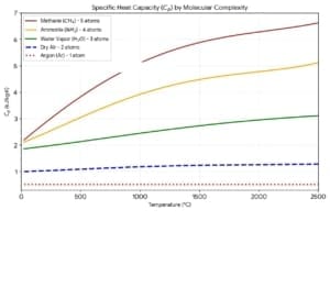
Please review the properties of gases and formulas to use for power calculations.
MHI Airtorch products offer a very low-pressure-drop (low loss).
- 1kW Savings per year is $876 @10c per kWh
- 10kW Savings per year is $8760 @10c per kWh
- 100kW Savings per year is $87600 @10c per kWh


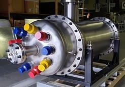
Large Flow MVTA. For 1000-1100°C. These are sealed process gas heaters (THN or DNA class) with a blower or inline capability—high KW – High Flow.
Large Flow GTA – For high-pressure vessel Airtorch use. Custom engineering. Please contact us directly for assistance.
Typical Conversion of Gas
LTA – Up to 900°C. LTA is a process heater for air that requires a compressed air input.
VTA—Up to 900°C. A VTA is a process gas heater with a fan or blower and low-flow sensor capability.
MTA925 and GTA – Up to 925°C/1100°C. These are flow or inline-sealed process gas heaters that can take compressed air or compressed gas input—new Models for the MVTA-DPF-DNA Class.
DPF – Up to 1150°C-1250°C/~2200°F. DPF models can take fan or blower input and a compressed air/gas input.

| N2 gas | Weight | Gas | ||
| pounds (lb) |
kilograms (kg) |
cubic feet (SCF) |
cu meters (Nm3) |
|
| 1 pound | 1.0 | 0.4536 | 12.83 | 0.36 |
| 1 kilogram | 2.205 | 1.0 | 28.24 | 0.8 |
| 1 SCF gas | 0.07245 | 0.03286 | 1.0 | 0.02832 |
| 1 Nm3 gas | 2.757 | 1.2506 | 35.3 | 1.0 |
| SCF (Standard cubic foot) gas is measured at 1 atmosphere and 70°F. Nm3 (Normal cubic meter) gas was measured at 1 atmosphere and 0°C. |
Quick conversion mm H2O column difference to psi:
1 mm H2O column difference to psi = 0.00142 psi
50 mm H2O column difference to psi = 0.07112 psi
100 mm H2O column difference to psi = 0.14223 psi
Quick Conversion of bar to kPA
| bar | kPa |
| 1 | 100 |
| 1.2 | 120 |
| 1.4 | 140 |
| 2.0 | 200 |


Airtorch® Mode. Heat from cold gas to hot gas quickly.
Airtorch® Recuperator Mode. SH models accept inlets up to 300°C and under special conditions to 600C.
Example-Air. Use the blue-black line for a steady state and cold start.
Use the purple line only in recuperator mode.
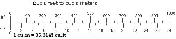
Conversions:
Actual: 1 m³= 35.31467 ft³
Hagen-Poiseuille equation: ΔP = 8μQL / πR^4 ( MHI Airtorch models offer low friction)
_________________________________________
Standard value (approximate Conversion)
1 Nm³/h is ~ 0.59 SCFM
Or
1 SCFM ~1.6 Nm³/hr.
_________________________________________
Power
1 MBH = 0.293 kW
Psst: An approximate way to theoretically calculate is SCFM = KW x 3160/∆T where ∆T is in °F. Use his method (and a little margin) for temperatures below 1200°F. For higher than 1200°F, Contact MHI.
Speed of Sound in Air as a function of Temperature and Pressure

Ideation
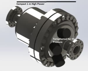


Tori-spherical
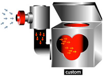

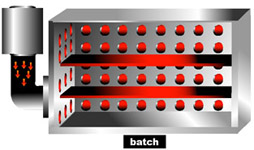

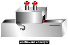

Continuous Overn with Airtorch