Selection of an Airtorch®
Energy Savings with MHI Airtorch®.
An easy five-step process for selection

The two primary steps are to determine the temperature and power.
Step 1: Determine the temperature required for your part.
This will help estimate the corresponding Airtorch® exit temperature. Note that manufacturers report the Airtorch® temperature with the t/c location inside the end of the exit tubing of any model (so that external exit conditions do not alter it). This is common to all devices so that discharge conditions do not unduly influence this rating temperature. The TA models (LTA, MTA925, GTA925, VTA) offer an exit temperature of about 925°C. The higher temperature MVTA, GVTA, and DPF models are rated to 1000°C/1300°C. If you plan to extend the Airtorch® exit piping, please note that well-insulated pipes will drop the temperature very little as the exit velocity is m/s. Please contact MHI when required. A helpful but rough rule of thumb may be about 50°C-100°C/m drop for good internal pipe insulation. Good pipe insulation is specific to the insulation and whether the pipe is internally or externally insulated. The industry standard is about 1- 2″ thick insulation—Energy Savings with MHI Airtorch®.
Save with MHI. MHI Airtorch® models offer very low-pressure drops. For example, saving a 5psi pressure drop for 2000 SCFM flow amounts to a savings of close to 30 kW power. Call MHI and compare.

Step 2: Power and Flow Rate.
(a) Is the application schematically described as Direct Impingement, Inline, or Process Air/Gas Preheating shown in the schematics on this page? For applications with a desired flow rate at a particular temperature, please refer to the diagrams provided or the easy calculators to calculate power. A good rule for such applications is choosing the highest temperature model available and a power that will quickly heat the impingement area to the required temperature. For extensive Flow Airtorch® use, please get in touch with MHI.
(b) Is the application schematically described as an augmentation/uniformity enhancer or retrofit/upgrade (typical schematics also shown in Choosing Airtorch®)? In such applications, one will add the Airtorch® to a furnace, vat, or chemical reaction chamber of known power and temperature or perhaps contemplate a completely new furnace. For a new furnace, the power is calculated by knowing the thermal properties of the chamber and its contents and then calculating how fast a temperature rise is required. Should you be building a furnace from scratch, a simple-to-use calculator for energy and power needed to maintain a steady state in a chamber with no load could be helpful as the first step for furnace design. For the augmentation, because Air or gas has to be exhausted to maintain a steady mass flow rate, the Airtorch® augmentation power is calculated from the Energy from Airtorch(R) at the high temperature into the furnace chamber minus the energy out from the furnace to the ambient. As an approximation, one could think of this augmentation power as equal to the [Mass flow rate x specific heat x {[(T(Airtorch®)- T(Furnace)]-(T(Furnace)- T0 (Ambient))]}. Temperatures are in Kelvin or Centigrade. The flow rate/kW for a given Airtorch® is provided in the graphs. This means that for any DPF or TA model with a rated temperature and power, it is relatively easy to calculate the augmentation power at a steady state inside the furnace that is being augmented. A good rule of thumb for furnace augmentation applications is to choose the Model with at least 300°C rated exit temperature more than the furnace temperature. Choose an Airtorch® power that exceeds about a third of the original furnace power.
(c) When employed as a waste-gas cleaner, please follow SCFM vs. temperature flowcharts
(d) For high flow and or for a high-pressure enclosure for significant industrial chemical reactions, please click to
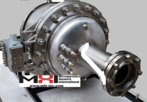
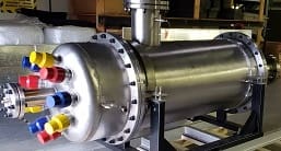
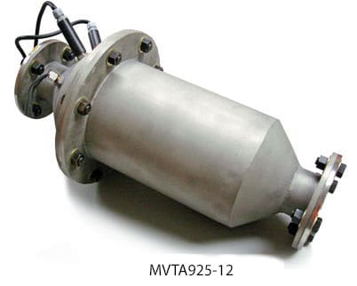
- Large Flow MVTA. For 1000-1200°C. These are sealed process gas heaters (THN or DNA class) with a blower or inline capability. High KW – High Flow. 200 KW to 4 MW. Voltages 380V, 400V, 440V, 480V, 600V.
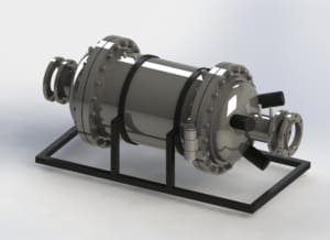
- Large Flow GTA – For high-pressure vessel Airtorch® use. Custom engineering. Please contact us directly for assistance.
New: Inline-Airtorch® models for process heat are now offered with input up to 20°C-800°C into the Airtorch®. The output is up to 1200°C.
Step 3: The tricky part is over.
You should choose between a blower or compressed gas/air as the flow generator. Depending on the Model, a flanged or threaded input/output is available. For air delivery for the DPF models, please follow the curve (s) shown above. Multiply the SCFM by the kW of the TA, THN, or DPF device you have chosen – i.e., based on the power calculation in step 2. Note that your actual performance may exceed the curve shown.
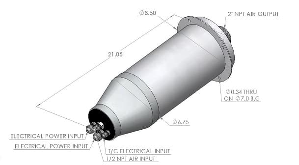
The (TA, MVTA, GTA, HI, and VTA ) models are rated to 925°C for the exit temperature. The SH, THN-DNA, HI, and DPF models can be rated to 1100°C/1200°C. Review Airtorch® models.
The availability of flanged outlets or NPT exit nozzles depends on the specific Model chosen. MHI will work with you to select an Airtorch® model that best suits your application. Please give yourself a little extra design space. MHI will work with you to ensure that you propose the best value. MHI will also provide financing guidance with ROIs and finance calculators as appropriate.
Step 4: Please get in touch with MHI at this stage.
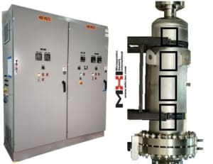
For contact information, please click on contact MHI for an online product information request indicating that you are ready to review your quote. MHI will quickly propose the best value. Some models are directly available from the MHI web store. Power and temperature control panels are also shown in the store if required.
Step 5: Please request and review quotes.
We look forward to servicing your order. Testimonials.
Note:
- At standard temperature and pressure (0 °C and 100 kPa), dry Air has a 1.2754 kg/m3 density. Hydrogen density is 0.0899 kg/m3. Nitrogen is 1.25 kg/m3
- At 20 °C and 101.325 kPa, dry Air has a 1.2041 kg/m3 density.
- At 70 °F and 14.696 psia, dry Air has a density of 0.074887lbm/ft3
- The density of Air at high temperatures.
![]()
For gases other than Air, multiply by the density ratio with Air at the same temperature, e.g., non-combustible hydrogen mixtures; the flow maybe two times higher than Air to get to the same temperature. The flow required for a dense gas, i.e., heavier than Air, e.g., Ar, will be lesser. Please remember that this is only an approximate calculation, and some tweaking may be needed when you receive your unit. MHI provides easy-to-use power controls. A formula for kW and flow rate is also given. Please call MHI for confirmation. Such a calculation is only an approximate number and should not be used for detailed design. MHI application specialists will guide you through the process. The density of Air at 14.7psia and 32°F is 1.293Kg/ m3.
The graphs are for steady-state operations. The Airtorch® models take little time to ramp up to a steady state. Please use the quick calculator only for an approximate value. All Airtorch® models should be used with MHI Control Panels that integrate safety features and extend life. There is a maximum temperature that should not be exceeded for any Airtorch®. This number is always known for every Model and should not be exceeded. Some larger size Airtorch® models are available with additional extended safety features, which are listed on the quote for the Model. Such safety features include a low-flow cut-off and over-temperature controller as applicable to the Model. Please review the quotation specifications, which contain full details. Quotations are available from MHI. Generally, for the TA models, i.e., LTA, VTA, THN, MTA925, MVTA, HI, and DPF types of Airtorch®, the maximum temperature and minimum airflow rate can be obtained with the flow curves provided on request.